Skip to content Quick setup for a single online processor connected to cabinets:
- Power on the Processor and LED Screens
- Set the Processor IP to be automatically retrieved
- Launch the Saco Editor Application.
- Create a new Project, Name the Project and choose a local folder to save your project.
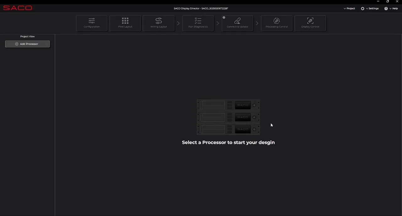
- Select your powered on Device from the online device. (please note that you can start with an offline design and later assign it to an online device.)
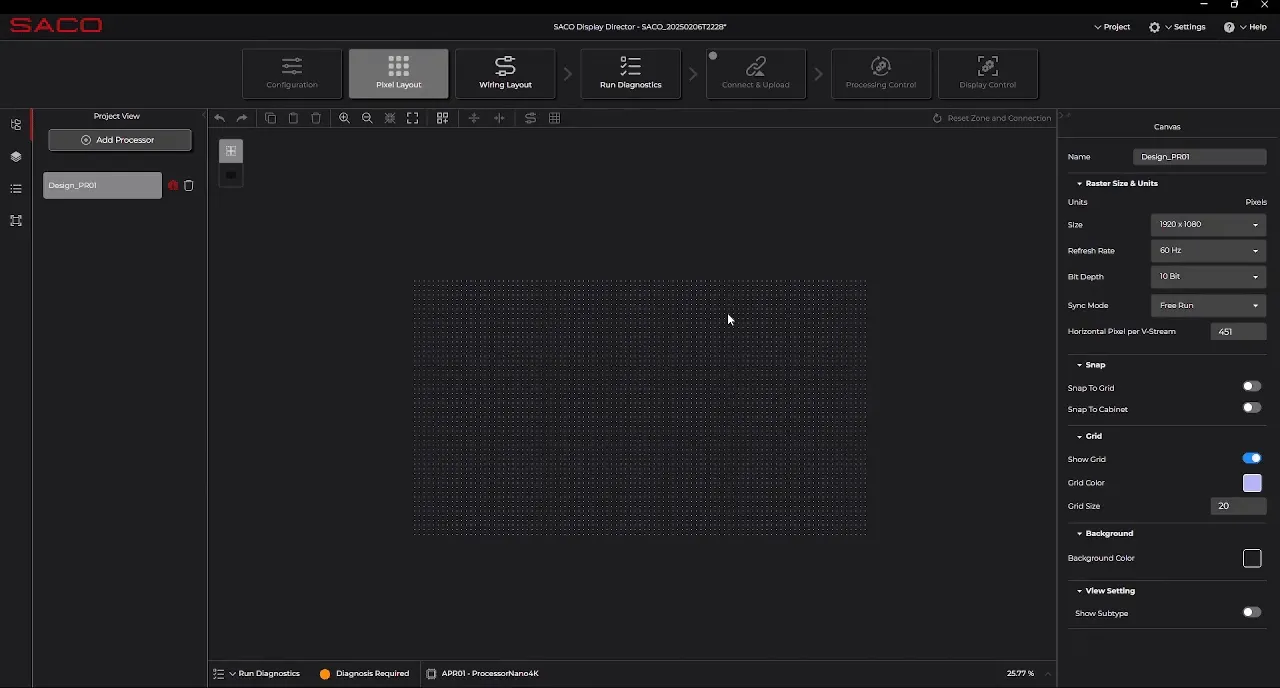
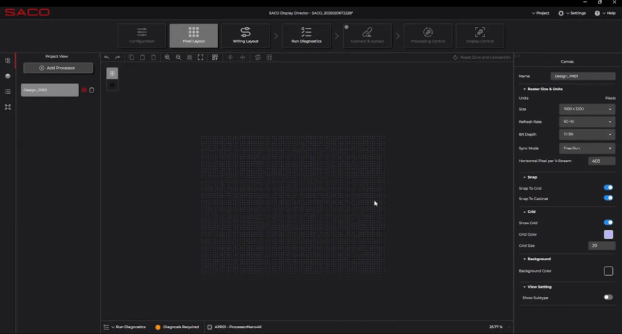
Pixel Tab
- Cabinet and Data Flow Step. Set the raster size, refresh rate, bit depth, this would automatically calculate the Zone size.
- Place the cabinets on the raster by either dragging and dropping pre-set components or use the quick batch for faster approach.
- Once the cabinet is placed, select them all by using the short cut Ctrl+A if they are not selected. From the toolbar use the desired dataflow pattern and have the Auto-Zoning on. The wiring will be shown with Zones created automatically.
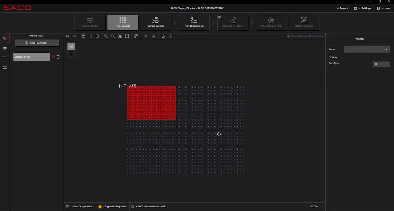
- Switch to Zone mode and click on each zone to view its information in the property panel. By default, all zones are assigned to Display 1, unless the user manually assigns them to different displays. To define additional displays, navigate to Project → Project Settings and add more displays to the project.
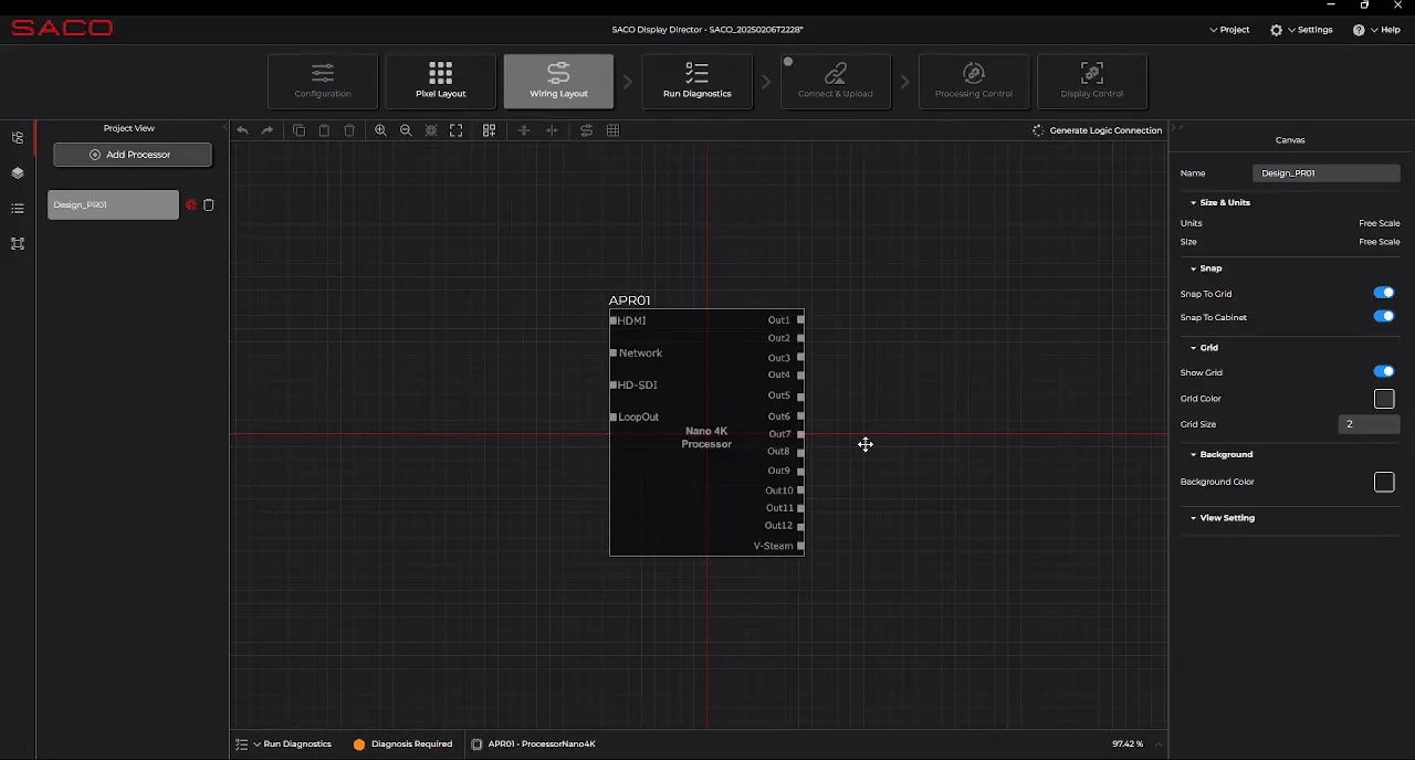
Wiring Layout: Cabling to the processor and cabinet
- Each zone or V-Stream can only be connected to one output of the processor. You can automatically structure the wiring connection by clicking on “Generate Logic Connection.” In this instance, a connection using an SFP+ and fiber receiver has been selected.
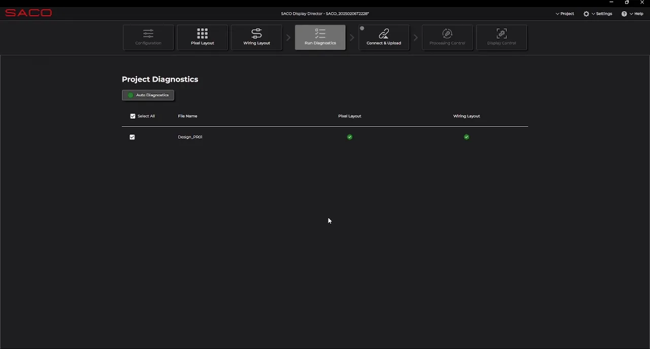
Validate the design
- Validate the design by clicking on “Run Diagnosis” for project validation. By selecting “Auto Diagnosis,” both the pixel and wiring layouts will be checked, and any errors will be flagged.

Connect & Upload
- Now that the design is complete, save the project using the shortcut Ctrl + S or by navigating to Project and selecting Save. Click “Connect & Upload” to upload the DMON JSON file to the server. You should receive a confirmation message indicating that the upload was successful.
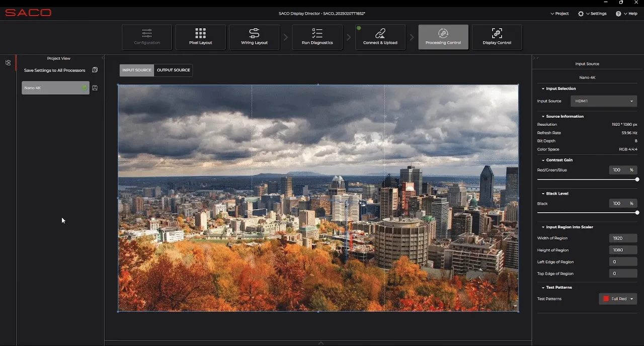
Processor Control
- In the Processor Control section, you can select the input source from the processor and begin scaling and cropping the input image. This can be done interactively or by entering the data in the right panel.
- Once the input source size is configured, you can also scale the output source. In this case, the output source is adjusted to fit the cabinet size.
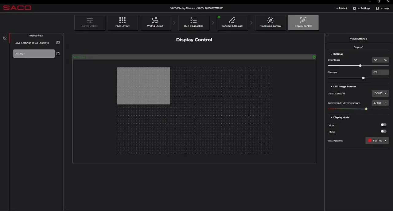
Display Control
- In the Display tab, you can test various features on the screens, such as brightness and gamma.